


Autodesk Revit for Windows PC is BIM software designed for architects, builders, and engineers. It provides 3D modeling tools, including functionality for architectural design, MEP and structural engineering, and construction. It also integrates file processing workflows within a unified environment.
Autodesk Revit Overview
Revit is the latest step in the ongoing evolution and development of multidisciplinary BIM, an intelligent model-based process for planning, designing, constructing, and managing buildings and infrastructure. Revit supports a multidisciplinary collaborative design process.
Based on Building Information Modeling (BIM) technology, Autodesk Revit software products are designed to design, construct, and manage high-quality, energy-efficient buildings. It's a comprehensive solution that combines architectural design, engineering systems design, building structures, and architectural modeling capabilities (Autodesk Revit Architecture, Autodesk Revit MEP, and Autodesk Revit Structure). This release marks some progress on this path. The roadmap defines forward-looking themes that guide and prioritize the development of Revit features and functionality based on input you provide through the Revit Ideas page.
Terrain Entity Enhancements (New in 2025)
Tools and functionality have been enhanced for working with terrain solid entities in models.
Mining Terrain Solid Volumes
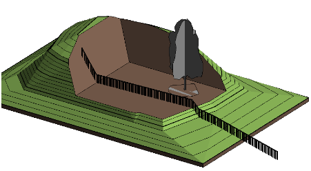
Excavate volumes from a terrain solid with intersecting floors, roofs, or terrain solid elements. Use this tool to create excavation locations within a terrain solid for a building, or to use a second intersecting terrain solid as a parking lot excavated from the first. Using the Excavation tool reduces the need to cut a terrain solid with a massing element and then place a floor or similar element. Excavation allows you to perform this operation on a single intersecting element in a single step. If your design changes, you can remove the excavation.
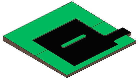
To excavate terrain entities
- Select a terrain solid with an intersecting element (roof, floor, or terrain solid).
- Click the Modify | Terrain Entities tab
 Terrain Solid Shape
  (Excavation).
 - Select the intersection entities to use for excavation.
- Click
 (Revise).
For additional information, see Terrain Solids: Excavation and Removing Excavation.
Using Shafts on Terrain Entities
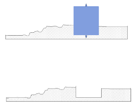
Boolean surface carrying primitives
Set the elevation datum from the top plane

Creating a Terrain Solid from Volume Faces
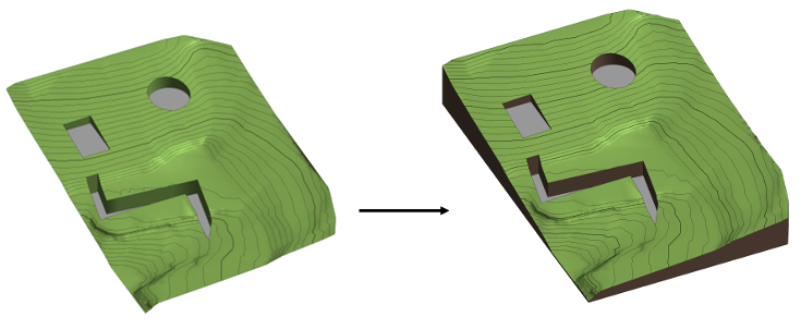
Generate a terrain solid element using the non-vertical faces of a mass element. When the mass element changes, the terrain solid element created from the mass element can update to the new faces.
Smooth shading of terrain entities
Model Site Panel Terrain Solid Smooth Shading. Terrain entity smooth shading off
 Terrain entity smooth shading on
Contour display during editing

Terrain surface conversion improvements
Features of Autodesk Revit
The evolving functionality and multi-discipline toolset in Autodesk Revit® helps every architecture, engineering, and construction professional do their best work, both individually and as a team.
- Streamline your modeling workflow by working directly in perspective view.
- When you import or link items into a model, you can apply tags to those items.
- Use the Split Elements tool on structural columns and framing elements
- To ensure that the structural connections of this application comply with the latest standards
- Use the Properties palette or the Edit Part dialog box to resize the corresponding fabricated part runs.
- When using some automatic fill tools, you can specify fabricated parts to exclude.
- Use the Properties palette to easily change the services of MEP fabrication parts in your model.
- Change the size (diameter) of the hanger support rod while maintaining accurate cost data.
- Add or remove dampers or change manufactured parts that support built-in dampers.
- Use the Split Element tool and the Split with Gap tool on any fabrication line.
Parametric components
Place walls, doors, and windows in an open, graphical, and parametric system to design and build shapes.
Worksharing
Save, synchronize, review, and update your work to a centrally shared model in the Revit project collaboration environment.
list
Use tables to better capture, filter, sort, display, and share project data.
Interoperability
Revit imports, exports, and links common BIM and CAD file formats, including IFC, 3DM, SKP, OBJ, and more.
Notes
Effectively communicate design intent using 2D and 3D markup, dimensioning, and annotation tools.
Global Parameters
Embed design intent with project-wide parameters that use radius and diameter dimensions and equal length constraints.
Developer Tools and Solutions
Extend the capabilities of Revit with Dynamo, API access, developer solutions, and BIM content on the Autodesk App Store.
Generative Design in Revit
Evaluate and compare design alternatives at scale using Generative Design in Revit. Available only to customers who subscribe to the AEC Collection.
Visibility Settings and Overrides
Control visibility by hiding, showing, and highlighting building elements. Use overrides to customize appearance.
Twinmotion for Revit
Launch Twinmotion directly from Revit. Synchronize design data and immerse yourself in an intuitive editor environment that transforms designs into realistic stills, scenes, and animations.
Standard and custom family content
Load content from the Autodesk Cloud into your Revit projects, or create your own library of building components.
Personalization and customization
Customize the user interface to suit your needs using configurable keyboard shortcuts, ribbons, and toolbars.
System requirements and technical details
| Revit 2025
Minimum requirements: Entry-level configuration |
|
|---|---|
| operating system * | 64-bit Microsoft® Windows® 10 or Windows 11. For support information, see Autodesk'sProduct Support Lifecycle. |
| CPU type | Intel® I-series, Xeon®, AMD® Ryzen, Ryzen Threadripper PRO. 2.5 GHz or higher.
It is recommended to use as high a CPU GHz as possible. |
| Memory | 16-GB RAM
|
| Video display resolution | Minimum requirements: 1280 x 1024 true color displayHighest requirements: Ultra-high-definition (4k) displays |
| Video adapter | Basic graphics card: Display adapter that supports 24-bit colorAdvanced Graphics: DirectX® 11 capable graphics card with Shader Model 5 and at least 4 GB of video memory |
| Disk space | 30 GB of available disk space |
| pointing device | Microsoft Mouse-compatible pointing device or 3Dconnexion®-compatible device |
| .NET platform | .NET 8 |
| Browser | Chrome, Edge, or Firefox |
| Desktop Connector Versions | When using Desktop Connector for collaborative workflows – Desktop Connector version 16.x or later is required for Revit 2025. Versions 15.8 or earlier are not supported for Revit 2025. Revit 2024 or earlier is compatible with Desktop Connector version 16.x. |
| connect | Internet connection for license registration and prerequisite component downloads |